Air breathing
Tank breathing introduces airborne dust, moisture, and particles.
 Integrated Fuel & Oil Filtration System
Preparing filtration solutions...
Invisible water and particles can accelerate wear. The right filtration keeps fluid at a measurable cleanliness level.
Microscopic particles and water are often invisible, yet can enter during delivery, storage, or transfer to the unit.
Without proper control, contaminants can clog engine filters, accelerate component wear, reduce combustion efficiency, and compromise asset readiness.
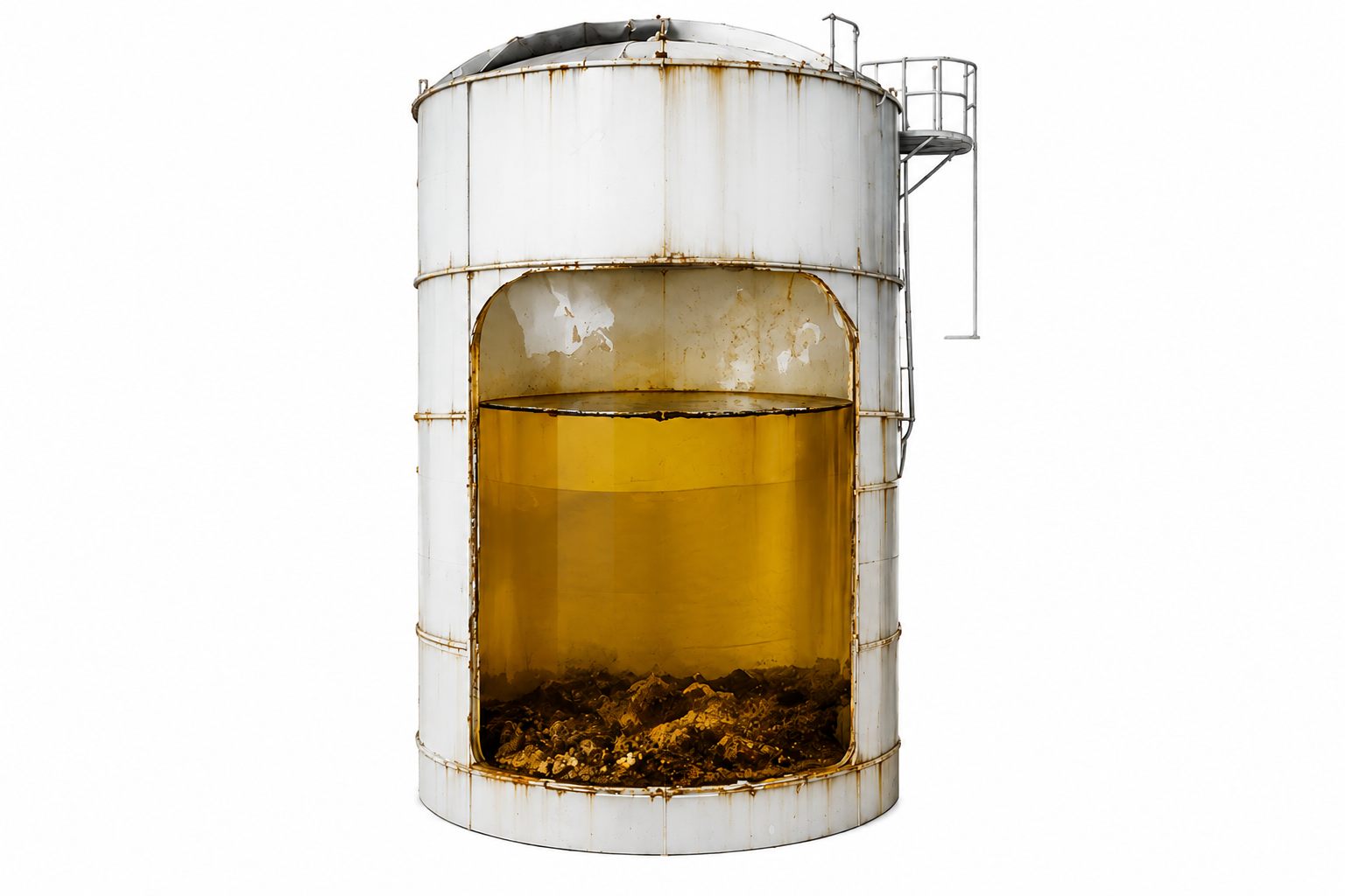
An integrated strategy maintains quality from the source to the diesel-engine inlet.
Tank breathing introduces airborne dust, moisture, and particles.
Temperature changes create water that accumulates at the tank bottom.
Rust, scale, and residue break loose from tanks and ageing pipework.
Hoses, pumps, trucks, and vessels can introduce contamination.
Rainwater enters through unprotected vents, caps, or openings.
Bacteria and fungi grow at the water interface, creating sludge and acids.
ISO codes communicate particle counts in a fluid. Lower numbers indicate lower particle contamination.
Higher particle level
Cleaner, controlled fluid
Note: the actual target must be defined from machine specifications, fluid conditions, and customer operating requirements.
Filtering fuel before contaminants enter the bulk or main tank.
Periodic circulation controls water and particles accumulated during storage.
Filtration at dispensing or inlet provides a final protection layer before the engine.
Fluid enters with water and particles from the tank or distribution line.
System media and configuration help separate water from fuel.
Filtration elements capture particles at the selected micron rating.
Fluid exits at a more controlled cleanliness level toward the asset.
Initial answers to help start a filtration-requirements discussion.
No. Flow capacity, contamination sources, fluid type, installation space, and cleanliness targets must be considered first.
The system can be placed at fuel receiving, the main tank, the fuel truck, or the point of use. Placement follows each operation’s risks and distribution pattern.
Element condition can be monitored through differential pressure, operating hours, fluid volume, and quality evaluation. The actual interval depends on contamination load.
That figure is an example target from the technical material. The final target must align with OEM specifications and customer operating conditions.
Our technical team can map critical points, capacity, and fluid cleanliness targets.